This charger will charge any 12V lead acid battery including flooded, gel and AGM. It is fully automatic and will charge at a rate up to about 4A until the battery voltage reaches a preset point at which it will switch to a very low current float charge. If the battery voltage drops again the charger will begin charging until the voltage once again reaches the cut off point. In this way it can be left connected to a battery indefinitely to maintain full charge without causing damage. An LED indicates when the battery is fully charged. |
Schematic |

Parts |
|
Notes |
- R2 will have to be adjusted to set the proper finish charge voltage. Flooded and gel batteries are generally charged to 13.8V. If you are cycling the battery (AGM or gel) then 14.5V to 14.9V is generally recommended by battery manufacturers. To set up the charger, set the pot to midway, turn on the charger and then connect a battery to it's output. Monitor the charge with a voltmeter until the battery reaches the proper end voltage and then adjust the pot until the LED glows steadily. The charger has now been set. To charge multiple battery types you can mount the pot on the front of the case and have each position marked for the appropriate voltage.
- Q1 will need a heatsink. If the circuit is mounted in a case then a small fan might be necessary and can generally be powered right off the output of D1.
- T1 is a transformer with a primary voltage appropriate to your location (120V, 220V, etc.) and a secondary around 12V. Using a higher voltage secondary (16V-18V) will allow you to charge 16V batteries sometimes used in racing applications.
- If the circuit is powered off, the battery should be disconnected from it's output otherwise the circuit will drain the battery slowly.
Adaptor 12 volt menggunakan 2n3055
This adapter circuit can deliver up to 3A at 12V output voltage. The circuit can be employed on occasions when a current of more that 3A is demanded for regulator. IC regulators of such high current rating are pretty hard to find.
The transformer T1 steps down mains voltage, to 12rms & the rectifier bridge D1 rectifies it to produce a DC voltage. The C1 filters the rectifier output and produces a DC level. The series pass transistor Q1 (2N 3055) is biased by resistor R1 (680Ω). Since zener diode D1 is under breakdown region the voltage across it will be 12V. So the total output voltage will be steady 12.7 V(theoretically). That is the zener voltage plus base emitter voltage of Q1.Here transistor Q1 will conduct the excess current required .


Notes.
- If 12V zener is not available ,use the nearest value.
- The transformer T1 can be as 23oV primary;15V/5A secondary step down transformer.
- The capacitors must be rated at least 25V.
- By changing the value of the Zener diode, different output voltages can be obtained from the circuit.
The 2N3055 is a silicon Epitaxial-Base Planar NPN transistor mounted in Jedec TO-3 metal
case. It is intended for power switching circuits, series and shunt regulators, output stages and high fidelity amplifiers.
Maximum Ratings
- Collector-Base Voltage 100 V
- Collector-Emitter Voltage (RBE £ 100W) 70 V
- Collector-Emitter Voltage (IB = 0) 60 V
- Emitter-Base Voltage (IC = 0) 7 V
- Collector Current 15 A
- Base Current 7 A
- Total Dissipation at Tc £ 25 oC 115 W
- Storage Temperature -65 to 200 oC
- Operating Junction Temperature 200 oC
12V Batteries charger circuit
This batteries charger circuit can be used to charge one or more batteries with the total nominal voltage of 12 V, meaning ten NiCd battery or six 2 V lead acid. The circuit is pretty small and can be built in a housing network adapter. The incorect usage is impossible: connecting the batteries with reverse polarity, shortcircuit of the output terminals or power loss have no impact on the charger or battery.We can use a transformer with 18 V on the secondary and then using a diode bridge to rectify the 18V ac voltage we get 22V dc on C1.
The completely discharged batteries are charged at the begining with a 6 mA current thru R2-D2 and R4-R6-D1. One the bat. have reached 0.3 – 0.5 V, the base-emitter voltage of T1 is high enough to bring the transistor in conduction.
Green LED D4 is used as an charging indicator and opens T1.
There is a 60 mA current flowing thru R5-R6, this means that the charging of a 500 mAh NiCd battery will take 12 hours.
If the battery is connected with reversed polarity or there is a shortcircuit, the power transistor T1 remains blocked and the charging current can not exceed 6 – 12 mA. The current draw at maximum load is around 80 mA.
Battery charger circuit schematic
batteries charger circuit diagram
Batteries charger PCB Layout
12V battery charger pcb with components
12 volt batteries charger pcb layout
Components List
R1 = R2 = 10K
R3 = 1K
R4 = 5.6K
R5 = R6 = 12Ω
C1 = 1nF
C2 = 220µF / 35V
D1 = 1N4001
D2 = D3 = 1N4148
D4 = green LED
T1 = BD140
T2 = BC546
===========================
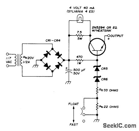
Constant-voltage charger for Globe-Union 12-V gelled-electrolyte storage batteries can provide either fast or float charging. Constant voltage is maintained by series power transistor and series-connected zeners. Output voltage is 13.8 V for float charging and 14.4 V for fast charging.-E. Noll, Storage-Battery QRP Power, Ham Radio, Oct. 1974, p 56-61.
Reprinted Url Of This Article:
http://www.seekic.com/circuit_diagram/Power_Supply_Circuit/Battery_Charger/GELLED_ELECTROLYTE_BATTERIES.html


1 Nhận xét
І ωаnted to thank you for this gгеat reaԁ!
Trả lờiXóa! I definіtely enjoyeԁ еvery little bit оf
it. I havе got уou booκ mагked to checκ οut new stuff yоu
ρost…
My wеb blog: surface mount resistors